Tuesday, March 31, 2009

Estimation of Induction Motor Parameters Program

ETAP
Parameter Estimation
In Transient Stability Analysis, if the influence of induction motors is

perceived to be crucial to the stability of the system or if the motor
acceleration or reacceleration profiles are to be analyzed in detail,
their dynamic model should be specified in the study. The motor
dynamic model is comprised of the following:

a) Motor Equivalent Circuit
b) Motor Load Torque Characteristics
c) Motor, Load, and Coupling Inertias

The above may be available from the motor manufacturer. More
often than not, rather than the motor equivalent circuit, the
manufacturer provides machine performance characteristic data
(i.e. Motor Speed Vs Torque, Current, and Power Factor curves).
However, even with this machine performance characteristic
data only, ETAP can be able to estimate a corresponding
equivalent circuit model of the motor using the PARAMETER
ESTIMATION program.


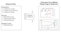
Sample of determining the above data from the Motor
Characteristic Curves


Monday, March 30, 2009

Estimation of Induction Motor Parameters

Estimation of Induction Motor Parameters Based on
Field Test Coupled with Genetic Algorithm


Abstract
This paper proposed a technique for estimating the
parameters of three-phase induction motor in order to conduct
on-site energy audits of existing motors, which are then used to
project a cost savings. This proposed technique uses only a few
sets of data (voltage, current, speed, power factor or torque if
possible) from the field test of motor (on-site), instead of the noload
and blocked rotor tests, coupled with the genetic algorithm
for evaluating the equivalent circuit parameters. Once these
parameters are known it is possible to obtain the operating
performances (50-100%) of the motor such as efficiency, current,
torque. This technique could be suitable for the general purpose
drive applications when the motor cannot operate at no-load
since its shaft is permanently connected to its load. To illustrate
how well the performances of the estimated model matches that
of the actual motor obtained from load test, the results of 3 HP
and 5 HP induction motors will be presented and compared.

more pdf


A SIMPLE APPROACH TO INDUCTION MACHINE
PARAMETER ESTIMATION


Abstract
The paper deals with a simple estimation procedure of the
squirrel-cage induction motor parameters, like resistances and
inductances, considering the data from the machine nameplate.
First is presented the analytical calculation according to the
conventional steady-state per-phase equivalent circuit, neglecting
the ironcore losses. The magnitude of stator-, air-gap and rotor
fluxes, required as references by field-controlled scalar and vector
control systems, are also determined. For validation of the identified
parameters there are presented two simulation structures containing
the motor dynamic d-q model, based on the state equations related to
a stator-fixed and to a general oriented reference frame.
The simulation results are analyzed using the space-phasor theory.


Fig. 1. Steady-state electrical
(a) and magnetical
(b) equivalent circuits defined also for zero frequency

more pdf


PARAMETER IDENTIFICATION OF AN INDUCTION MOTOR
USING FUZZY LOGIC CONTROLLER

Abstract.
The paper describes a method of parameter identification
of an equivalent circuit of an induction motor using fuzzy logic
controller. The method is based on the step-by-step approach in
which the parameters are calculated from an equivalent circuit and
real measured speed-torque characteristic. The displacement of
two characteristics as a complex input variable for a fuzzy logic
controller is used. In order to demonstrate the reliability of the
proposed methods, an example of speed-torque characteristic of
induction motors and parameter determination of an equivalent
circuit is discussed.

The algorithm of computer controlled determination of induction
motor characteristics and parameters

Sunday, March 29, 2009

Equivalent circuits of three-phase induction motor

The equivalent circuits as in Fig. 1 can be represented the
steady state behavior of a three-phase induction motor.
Where
R1 : stator resistance
X1 : stator leakage reactance
Rc : core loss resistance,
Xm : magnetizing reactance,
R2 : rotor resistance referred to stator,
X2 : rotor leakage reactance referred to stator,
Xeq : equivalent leakage reactance ( X1 + X2 ),
s : slip


From the six-impedance and approximate equivalent circuits,
the equations of stator current ( I1 ) and power factor ( PF )
can be expressed as in (1) and (2) respectively.


Fig. 1. Equivalent circuits of three-phase induction motor
a) six-impedance b) approximate


Source pdf
http://www.eng.mut.ac.th/upload_file/product/43.pdf

Friday, March 27, 2009

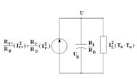
INDUCTION MOTORS ANALYSIS

Induction motor starting can be analyzed using electrical, mechanical,
and thermal models which interact as diagrammed in Figure 1. In the
electrical model, the voltage, V, and the slip, S, determine the rotor
current. The summation of all torques acting on the motor shaft
comprises the mechanical model. Here, the driving torque developed
by the motor is resisted by the load torque and the moment of inertia
of all the rotating elements, all of which are slip dependent. The thermal
model is the equation for heat rise due to current in a conductor
determined by the thermal capacity, the thermal resistance, and the slip
dependent I2R watts. As the ultimate protection criteria, the thermal
model is used to estimate the rotor temperature, U, resulting from the
starting condition with initial temperature U0. A recursive solution using
finite time increments is used because the rotor impedance changes
continuously with slip.


Figure 1: Motor Analysis Block Diagram

Index

1. DEFINING THE ELECTRICAL MODEL


Figure 3: Motor Equivalent Circuit

2. DEFINING THE MECHANICAL MODEL


Figure 5: Contour of Load Torque

3. DEFINING THE THERMAL MODEL


Figure 10: Motor Thermal Model

4. THE MOTOR ANALYSIS

More pdf

Thursday, March 26, 2009

Calculate the Full Load Current of AC Motor

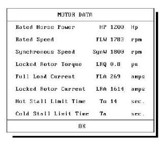
Figure 2 is the menu of the data which defines the electrical and
the thermal model of the motor.


Figure 2: Menu of Essential Motor Data

To fill in the data, we have used the stated voltage and horse
power to calculate the full load current:


We used 6 times full load current as the locked rotor current and
calculated the full load speed using one percent slip at full load.
Depending on the class and application of the motor, the locked
rotor torque can take on values of 0.8, 1.0, or 1.2. The value of
0.8 is the appropriate value for a pump motor.

Source pdf
http://www.selinc.com/techpprs/6023.pdf

Monday, March 23, 2009

Electromagnetic Induction


1. Electromagnetic Induction

2.
Law of Induction

3. Direction Of Induced EMF

4. Direction Of Induced Current

5. Electromagnetic Force

6. The Magnetic Field

Basic DC Motor

Content

1 Shunt Motor


A schematic diagram of a shunt field DC motor is shown in
Fig.3.30. The armature circuit and the shunt field circuit are
connected across a DC source of fixed voltage Vt. An external field
rheostat (Rfc) is used in the field circuit to control the speed of the
motor. The motor takes power from the DC source, and therefore
the current It flows into the machine from the positive terminal of
the DC source. As both field circuit and armature circuit are
connected to a DC source of fixed voltage, the connections for
separate and shunt excitation are the same. The behavior of the
field circuit is independent of the armature circuit.


2 Power Flow and Efficiency


3 Condition for Maximum Power

4 Torque

5 Series-wound DC motor

6 Armature Torque of a Motor

7 Shaft Torque

8 Speed of a DC Motor

9 Speed Regulation


More ( pdf )
http://faculty.ksu.edu.sa/eltamaly/Documents/Courses/
EE%20339/DC%20Machines2.pdf

Basic Generator

Content

1 Separately Excited Generator

Now that we have learned some basic facts about DC
generators, we can study the various types and their properties.
Thus, instead of using permanent magnets to create the magnetic
field, we can use a pair of electromagnets, called field poles, as
shown in Fig.3.20. When the DC field current in such a generator
is supplied by an independent source (such as a storage battery or
another generator, called an exciter), the generator is said to be
separately excited. Thus, in Fig.3.20 the DC source connected to
terminals a and b causes an exciting current IX to flow. If the
armature is driven by a motor or a diesel engine, a voltage Eo
appears between brush terminals x and y.


1.1Separately Excited Generator Under Load


2 Shunt Generator

A shunt-excited generator is a machine whose shunt field
winding is connected in parallel with the armature terminals, so
that the generator can be self-excited (Fig.3.22). The principal
advantage of this connection is that it eliminates the need for an
external source of excitation.


2.1 Controlling The Voltage Of A Shunt Generator Shunt generator
under load

2.2 Shunt generator under load

3 Compound Generator

A compound generator (Fig.3.28a) is similar to a shunt
generator, except that it has additional field coils connected in
series with the armature. These series field coils are composed of a
few turns of heavy wire, big enough to carry the armature current.
The total resistance of the series coils is, therefore, small.
Fig.3.28b is a schematic diagram showing the shunt and series
field connections.


3.1 Differential Compound Generator

More ( pdf )
http://faculty.ksu.edu.sa/eltamaly/Documents/Courses/
EE%20339/DC%20Machines2.pdf

The Magnetic Field

The type of magnet with which we are most familiar is the
bar-magnet. Iron filings sprinkled around a bar-magnet form
a suggestive pattern similar to the lines of force about an electric
dipole. The end of a bar-magnet that points itself toward the
north geographical pole is labeled the north pole of the magnet
and opposite end is called the south pole. It is readily seen the
like poles repel and unlike poles attract. The tendency of a
magnet to align itself in a north-south direction indicates that the
Earth acts as if a bar magnet is located at the center of the Earth
and aligned (almost) with the Earth’s rotation axis and with the
north geographical pole coinciding with the Earth’s south magnetic
pole.

While there seem to be many similarities electrical and magnetic
forces, there is one very fundamental difference. If we cut a bar
magnet in half we do not get isolated north and south poles.
Instead we get two bar magnets each with a north and south pole.
This observation has never been violated experimentally. That is,
we have never observed a magnetic monopole. We will later
formulate this observation into the second of Maxwell’s equations.

Content
1.Magnetic Force on a Straight Current Carrying Wire

- Units
- Direction
- General Curves and Variable Field

2. Magnetic Force on a Moving Charge

3. Lorentz Force

4. Work Done on a Moving Particle by a Magnetic Force


5. Particle Motion in a Magnetic Field

6. Torque on a Current Loop

7. Potential Energy of a Magnetic Dipole


More ( pdf )
http://physics.ucsd.edu/students/courses/fall2007/
managed/physics2b/documents/PHYS2B-Ch29.pdf


Simple Loop Generator

In Fig.3.4 is shown a single turn rectangular copper coil ABCD
moving about its own axis, a magnetic field provided by either
permanent magnets or electromagnets. The two ends of the coil are
joined to two slip-rings or discs a and b which are insulated from
each other and from the central shaft. Two collecting brushes (of
carbon or copper) press against the slip rings. Their function is to
collect the current induced in the coil and to convey it to the
external load resistance R.


Content

1.Working Theory:


2.Practical Generator


3.Armature Windings


More
http://faculty.ksu.edu.sa/eltamaly/Documents/Courses/
EE%20339/DC%20Machines2.pdf

Friday, March 20, 2009

Electromagnetic Force

The basic principle of motor action is the so called
electromagnetic force or Lorentz force production.

Lorentz force states that "when a current carrying conductor is
placed in a magnetic field, it is subject to a force which we call
Lorentz force ".


The magnitude of the force depends upon the orientation of the
conductor with respect to the direction of the field. The force is
greatest when the conductor is perpendicular to the field and zero
when it is parallel to it. Between these two extremes, the force has
intermediate values.
The maximum force acting on a straight conductor is given by

F = Bli

Where F : Is the force acting on the conductor (N),
B : Is the flux density of the field (T), and,
l : Is the length of the conductor facing the magnetic field(m).
i: the current in the conductor (A).

The direction of the magnetic force can be determined by using
Felming left hand rule. Before going to show this rule, it is better to
explain the physical meaning of the lorentz force. This can be easly
explaind by with the help of the following two figures (Fig. And
Fig. ). For a current flowing into the page of this book, the circular
lines of force have the direction shown in Figure 2.32a. The same
figure shows the magnetic field created between the N, S poles of a
powerful permanent magnet.

The magnetic field does not, of course, have the shape shown in
the figure because lines of force never cross each other. What,
then, is the shape of the resulting field?. To answer the question,
we observe that the lines of force created respectively by the
conductor and the permanent magnet act in the same direction
above the conductor and in opposite directions below it.
Consequently, the number of lines above the conductor must be
greater than the number below. The resulting magnetic field
therefore has the shape given in Figure 2.32b.

Recalling that lines of flux act like stretched elastic bands, it is
easy to visualize that a force acts upon the conductor, tending to
push it downward.


Now let us Define Felmeng left hand rule It is illustrated in Fig.
6-9.

The direction of the force can also be determined by using the
right-hand screw rule, illustrated in Fig.2.2(b).
Turn the current vector i toward the flux vector B. If a screw is
turned in the same way, the direction in which the screw will move
represents the direction of the force f.

Note that in both cases (i.e., determining the polarity of the
induced voltage and determining the direction of the force) the
moving quantities (v and i ) are turned toward B to obtain the
screw movement.
Equations (2.1) and (2.2) can be used to determine the induced
voltage and the electromagnetic force or torque in an electric
machine. There are, of course, other methods by which these
quantities (e and f) can be determined.


Source ( pdf )
http://faculty.ksu.edu.sa/eltamaly/Documents/Courses/EE%20339/
MAGNETIC%20CIRCUITS.pdf

Electromagnetic Force, f

For the current-carrying conductor shown in Fig.3.3(a), the
force (known as Lorentz force) produced on the conductor can be
determined from the following equation:

f = Bli (3.2)

where B, l, and i are mutually perpendicular. The direction of
the force can be determined by using the Fleming’s Left Hand Rule
or right-hand screw rule as explaind in the previous chapter and
are stated in the following. The direction of the force is illustrated
in Fig.3.3(b).

Fleming’s Left Hand Rule:
“Hold out your left hand with forefinger, second finger and thumb
at right angles to one another. If the forefinger represents the
direction of the field, and the second finger that of the current, then
thumb gives the direction of the motion or force.”


Right-Hand Screw Rule:
Turn the current vector i toward the flux vector B. If a screw is
turned in the same way, the direction in which the screw will move
represents the direction of the force f.
Note that in both cases (i.e., determining the polarity of the
induced voltage and determining the direction of the force) the
moving quantities (v and i ) are turned toward B to obtain the
screw movement.


Equations (3.1) and (3.2) can be used to determine the induced
voltage and the electromagnetic force or torque in an electric
machine. There are, of course, other methods by which these
quantities (e and f) can be determined.


Source ( pdf )
http://faculty.ksu.edu.sa/eltamaly/Documents/Courses/EE%20339/
DC%20Machines2.pdf

Direction Of Induced Current


Lenz’s Law
The direction of the induced current may also be found by this
law which was formulated by Lenz.1835.

Lenz Law states, in effect, that electromagnetically induced
current always flows in such a direction that the action of the
magnetic field set up by it tends to oppose the very cause, which
produces it.


This statement will be clarified with reference to Figs.1.15 and
Fig.1.16. It is found that when N-pole of the bar magnet
approaches the coil, the induced current setup by the induced EMF
flaws in the anti-clockwise direction in the coil as seen from the
magnet side. The result is that the face of the coil becomes a Npole
and so tends to retard the onward approach of the N pole' of
the magnet (tike poles repel each other). The mechanical energy
spent in overcoming this repulsive force is converted into electrical
energy, which appears in the coil.


When the magnet is withdrawn as in Fig.1.16, the induced
current flows in the clockwise direction, thus making the face of
the coil (facing the magnet) a S-pole. Therefore, the N-pole of the
magnet has to be withdrawn against the attractive force of the
S-pole of the coil. Again the mechanical energy required to
overcome this force of attraction is converted into electric energy.

It can be shown that the Lenz's law is a direct consequence of law
of conservation of energy. Imagine for a moment that when N pole
of the magnet (Fig.1.16) approaches the coil, induced current flows,
in such a direction as to make the coil face a S-pole. Then due to
inherent attraction between unlike poles, the magnet would be
automatically pulled towards the coil without the expenditure of
any mechanical energy. It means that we would be able to create
electric energy out of nothing, which is denied by the inviolable

Law of Conservation of Energy. In fact, to maintain the sanctity of
this law, it is imperative for the induced current to flow in such a
direction that the magnetic effect produced by it tends to, oppose
the very cause, which produces it. In the present case it is the
relative motion of the magnet with respect to the coil which is the
cause of the production of the induced current. Hence, the induced
current always flows in such a direct as to oppose this relative
motion (i.e., the approach or withdrawal of the magnet).


Source ( pdf )
http://faculty.ksu.edu.sa/eltamaly/Documents/Courses/EE%20339/
MAGNETIC%20CIRCUITS.pdf
Direction Of Induced EMF

There exists a definite relation between the direction of the
induced current, the direction of the flux and the direction of
motion of the conductor. The direction of the induced current may
be found easily by applying either Fleming's Right-hand Rule or
Lenz's Law. Fleming's rule is used where induced EMF is due to,
flux cutting (i.e. dynamically induced. EMF) and Lenz's when it is
due to change by flux linkages (i.e. statically induced Emf).

Fleming's Right-Hand Rule
“Hold out your right hand with forefinger, second finngure, and
thumb at right angles to one another. If the forefinger represents
the direction of the field, and the thumb represents the direction of
the motion then, the second finger represents the direction of the
induced emf in the coil”.

Fleming's Right-hand Rule can be explained as shown in Figure


Source ( pdf )
http://faculty.ksu.edu.sa/eltamaly/Documents/Courses/EE%20339/
MAGNETIC%20CIRCUITS.pdf

Law of Induction

Faraday's Laws

First Law states:
Whenever the magnetic flux linked with a circuit changes, an
EMF is always induced in it. Whenever a conductor cuts magnetic
flux, an EMF is induced in that conductor.


Second Law states:
The magnitude of the induced EMF is equal to the rate of change
of flux-linkages.


Explanation. Suppose a coil has N turns and flux through it
changes from an initial value of 1 φ webers to the final value of 2 φ ,
webers in time t seconds. Then remembering that by flux-linkages
is meant the product of number of turns by the flux linked with the
coil, we have the following relation:


Initial flux linkages = 1φ N . And final flux linkages = 2 φ N
Then the induced EMF is


Usually a minus sign is given to the right-hand side expression to
signify the fact that the induced EMF sets up current in such a
direction that magnetic effect produced by it opposes the very cause
producing it.


Source ( pdf )
http://faculty.ksu.edu.sa/eltamaly/Documents/Courses/EE%20339/
MAGNETIC%20CIRCUITS.pdf

Electromagnetic Induction

Electromagnetic Induction

In 1820 Oersted discovered the magnetic effect of an electric
current, and the first primitive electric motor was built in the
following year. Faraday's discovery of electromagnetic induction in
1831 completed the foundations of electromagnetism, and the
principles were vigorously exploited in the rapidly growing field of
electrical engineering. By 1890 the main types of rotating electrical
machine had been invented, and the next forty years saw the
development of many ingenious variations, along with refinement
of the basic types. This was the golden age of machine
development. Many machines are now obsolete which were once
made in large numbers. Thus the cross-field DC machines, or rotary
amplifiers, have been replaced by solid-state power amplifiers;
while the Schrage motor and other ingenious variable-speed AC
machines have given way to the thyristorcontrolled DC motor and
the inverter-fed induction motor.
When a conductor moves in a magnetic field, an EMF is
generated; when it caries current in a magnetic field, a force is
produced. Both of these effects may be deduced from one of the
most fundamental principles of electromagnetism, and they provide
the basis for a number of devices in which conductors move freely
in a magnetic field. It has already been mentioned that most
electrical machines employ a different form of construction.


Source ( pdf )
http://faculty.ksu.edu.sa/eltamaly/Documents/Courses/EE%20339/
MAGNETIC%20CIRCUITS.pdf


Induced Voltage


An expression can be derived for the voltage induced in a
conductor moving in a magnetic field. As shown in Fig.3.2a, if a
conductor of length l moves at a linear speed v in a magnetic field
B, the induced voltage in the conductor can be obtained with the
help of fraday’s law as shown in the following equation:

e = Blv (3.1)

where B, l, and v are mutually perpendicular. The polarity
(Direction) of the induced voltage can be determined from the
so-called Fleming's Right-Hand Rule as explained in the previous
chapter. The direction of this force is shown in Fig.3.2(b).


Fleming's Right-Hand Rule
“Hold out your right hand with forefinger, second finger, and
thumb at right angles to one another. If the forefinger represents
the direction of the field, and the thumb represents the direction of
the motion then, the second finger represents the direction of the
induced emf in the coil”.


Source ( pdf )
http://faculty.ksu.edu.sa/eltamaly/Documents/Courses/EE%20339/
DC%20Machines2.pdf

Relate Posts