Showing posts with label Motor Control. Show all posts

Saturday, October 2, 2010

Dynamic Model , Proportional Integral and Derivative Control of Brushless DC Motor


Proportional Integral and Derivative Control of Brushless DC Motor

Abstract
Brushless DC (BLDC) motors are one of the electrical drives that are rapidly
gaining popularity, due to their high efficiency, good dynamic response and low
maintenance. In this paper, the modeling and simulation of the BLDC motor was done
using the software package MATLAB/SIMULINK. A speed controller has been designed
successfully for closed loop operation of the BLDC motor so that the motor runs very
closed to the reference speed. The simulated system has a fast response with small
overshoot and zero steady state error.

http://www.eurojournals.com/ejsr_35_2_05.pdf


Dynamic Model of the BLDC Motor

It is assumed that the BLDC motor is connected to the output of the inverter, while the inverter input terminals are connected to a constant supply voltage, as shown in Fig.1. Another assumption is that there are no power losses in the inverter and the 3-phase motor winding is connected in star.


http://www.eurojournals.com/ejsr_35_2_05.pdf

Wednesday, February 17, 2010

Brushed DC Motor control by using PIC Microcontroller


Low-Cost Bidirectional Brushed DC Motor Control
Using the PIC16F684
INTRODUCTION
This application note discusses how to use the
Enhanced, Capture, Compare, PWM (ECCP) on the
PIC16F684 Microcontroller for bidirectional, brushed DC (BDC) motor
control. Low-cost brushed DC motor control can be
used in applications such as intelligent toys, small
appliances and power tools. The PIC16F684 takes
Microchip's Mid-Range Family of products to the next
level with its new ECCP peripheral. The ECCP
peripheral builds on the technology of the CCP module
with added features such as four PWM channels for
easy bidirectional motor control through the hardware.
This application note focuses on using the ECCP in
PWM mode using the full-bridge configuration. Using
the ECCP allows easy interfacing to a full-bridge
configuration for bidirectional BDC motor control.


Brushed DC Motor control by using PIC microcontroller
I used PIC microcontroller to realize the control of BLDC motor. In the video, you can observe how the PID parameter affect the performance of motor. The different magnitudes (due to different PID parameters)


Efficient Brushless DC motor and Permanent Magnet Synchronous Motor Control
Demonstration of advanced sensorless algorithms such as field oriented control and trapezoidal control using sinusoidal drive for Brushless DC (BLDC) and Permanent Magnet (PM) Synchronous Motors


Buy PIC Microcontroller Project Book

Sunday, February 14, 2010

Brushless DC Motor Control using PIC18 Microcontroller Video

Video Developing Brushless DC (BLDC) motor control using PIC18Fxx31 Microcontroller - Part 1
BLDC motors can be designed to operate from a high voltage or low voltage source. The following seminar explores BLDC control using PIC18F Microcontroller devices.


Video Developing Brushless DC (BLDC) motor control using PIC18Fxx31 Microcontroller - Part 2


Video Developing Brushless DC (BLDC) motor control using PIC18Fxx31 Microcontroller - Part 3


Video Developing Brushless DC (BLDC) motor control using PIC18Fxx31 Microcontroller - Part 4


Buy PIC18 Microcontroller Book

Monday, February 8, 2010

Sensorless Brushless DC Motor control using a Microcontroller Data and algorithm

Sensorless Brushless DC Motor Control with Z8 Encore! MC™ Microcontrollers
Abstract
This application note discusses the closed loop control of a 3-Phase Brushless
Direct Current (BLDC) motor using the Z8 Encore! MC™ Family of
Microcontrollers series microcontrollers (MCUs). The Z8 Encore! MC™ product
family is designed specifically for motor control applications, featuring an on-chip
integrated array of application-specific analog and digital modules. This in turn
results in fast and precise fault control, high system efficiency, and “on-the-fly”
speed / torque and direction control, as well as ease of firmware development for
customized applications.

This article further discusses ways on how to implement a sensorless feedback
control system using a “Phase Locked Loop” along with Back EMF sensing.


Sensorless control of 3-phase brushless DC motors
Introduction
This application note describes how to implement sensorless commutation control
of a 3-phase brushless DC  motor (BLDC) with the low cost ATmega48
microcontroller. A general solution, suitable for most 3-phase BLDC motors on the
market is presented. The full source code is written in the C language, no assembly
is required. Adaptation to different motors is done through the setting of parameters
in the source code.

The ATmega48/88/168 devices are all pin and source code compatible. The only
difference is memory sizes. This application note is written with ATmega48 in mind,
but any reference to ATmega48 in this document also applies to ATmega88/168.


Brushed DC motor control using the LPC2101 microcontroller
Introduction
This application note demonstrates the use of a low cost NXP Semiconductors LPC2101 microcontroller for bidirectional brushed DC motor control.
The LPC2101 is based on a 16/32-bit ARM7 CPU combined with embedded high-speed flash memory. A superior performance as well as their tiny size, low power consumption and a blend of on-chip peripherals make these devices ideal for a wide range of applications. Various 32-bit and 16-bit timers, 10-bit ADC and PWM features through output match on all timers, make them particularly suitable for industrial control. 

Brushed DC (Direct Current) motors are most commonly used in easy to drive, variable speed and high start-up torque applications. They have become widespread and are available in all shapes and sizes from large-scale industrial models to small motors for light applications (such as 12 V DC motors).


Sensorless BLDC Motor Control Using MC9S08AC16
Introduction
This application note describes the design of a 3-phase
sensorless BLDC motor drive with Back-EMF
zero crossing. It is based on Freescale’s MC9S08AC16
that can be effectively used for motor-control
applications.

The concept of the application is that of a speed-closed
loop drive using Back-EMF zero crossing technique for
positional detection. It serves as an example of a
sensorless BLDC motor control system using
Freescale’s MCU and 3-Phase BLDC/PMSM
Low-Voltage Motor Control Drive. It also illustrates
the usage of general on-chip peripherals for
motor-control applications.
This application note includes a description of the
controller features, basic BLDC motor theory, system
design concept, hardware implementation, software
design including the FreeMaster software visualization
tool, application setup, and demo operation.


Sensorless Brushless DC Motor Control with PIC16 Microcontroller
INTRODUCTION
There is a lot of interest in using Brushless DC (BLDC)
motors. Among the many advantages to a BLDC motor
over a brushed DC motor, we can enumerate the
following:
• The absence of the mechanical commutator
allows higher speeds
• Brush performance limits the transient response
in the DC motor
• With the DC motor you have to add the voltage
drop in the brushes among motor losses
• Brush restrictions on reactance voltage of the
armature constrains the length of core reducing
the speed response and increasing the inertia for
a specific torque
• The source of heating in the BLDC motor is in the
stator, while in the DC motor it is in the rotor,
therefore it is easier to dissipate heat in the BLDC
• Reduced audible and electromagnetic noise


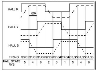
Brushless DC Motors Theory and Driver Circuit

Buy Brushless  Motor  Speed Controller

Friday, January 8, 2010

Sensorless Brushed DC Motor control using a dsPIC Data and algorithm

This web seminar explains a sensorless Brushless Direct Current (BLDC) motor control algorithm, implemented using the dsPIC® digital signal controller (DSC).

Sensorless Brushed DC Motor control using a Majority Function Part 1 of 2


Sensorless Brushed DC Motor control using a Majority Function Part 2 pf 2


How a BLDC controller work - Giovanni Garraffa


Using the dsPIC30F for Sensorless BLDC Control
INTRODUCTION
This application note describes a fully working and
highly flexible software application for using the
dsPIC30F to control brushless DC (BLDC) motors
without position sensors. The software makes
extensive use of dsPIC30F peripherals for motor
control. The algorithm implemented for sensorless
control is particularly suitable for use on fans and
pumps. The program is written in C and has been
specifically optimized and well annotated for ease of
understanding and program modification.


more


Sensorless BLDC Motor Control Using dsPIC30F2010
INTRODUCTION
This application note describes how to provide sensorless
BLDC motor control with the dsPIC30F2010
Digital Signal Controller. The technique used is based
on another Microchip application note: Using the
dsPIC30F for Sensorless BLDC Control (AN901).
This application note explains how to apply the
dsPIC30F2010 device to the hardware and software
described in AN901, which uses the dsPIC30F6010
device and dsPICDEM™ MC1 Motor Control Development
Board. The 80-pin dsPIC30F6010 has 144
Kbytes of Flash Program Memory, 8 Kbytes of RAM
available and abundant I/O. The 28-pin
dsPIC30F2010, on the other hand, has limited I/O, only
12 Kbytes of Flash program memory and 512 bytes of
RAM. As you can see, the resources are finite.
This application note prescribes changes to the hardware,
software and user interface described in AN901
to facilitate the easy transfer of the code to the
dsPIC30F2010 device.


more

Buy  Brushless DC Motor control

Tuesday, June 30, 2009

Dc Motor Speed Control Lecture Video

DC MOTOR DRIVE FUNDAMENTALS
UNDERSTANDING DC MOTOR DRIVES
DC motors have been available for nearly 100 years. In fact the first electric motors were designed and built for operation from direct current power.
AC motors are Now and will of course remain the basic prime movers for the fixed speed requirements of industry. Their basic simplicity, dependability and ruggedness make AC motors the natural choice for the vast majority of industrial drive applications.

Then where do DC drives fit into the industrial drive picture of the future?
In order to supply the answer, it is necessary to examine some of the basic characteristics obtainable from DC motors and their associated solid state controls. more

Precision DC motor speed controller
Optical tachometers that produce a frequency proportional to RPM are popular feedback sources for precision analog motor speed control. This usually involves a frequency-to-voltage converter (FVC) to convert the tachometer output to a voltage that’s then input to a conventional servo. Though it typically works fine, it’s unnecessarily complicated and requires a tachometer with a relatively high pulse/revolution characteristic to allow for both a reasonably fast loop response and adequate ripple filtering in the FVC. more


DC Motor Speed Control PWM


The user may feel that the RC PWM signal may be an awesome resource to control the speed of a DC motor. And this is of course true, except that the RC PWM signal itself is pretty much useless as a direct means of controlling the DC motor speed. What needs to be done is to have an intermediate circuit to decode the position information (RC Pulse width) and generate a speed magnitude signal. In other words, if the input pulse is 1 ms, move the DC motor on reverse at maximum speed, if 1.5 ms wide stop the DC motor and if 2.0 ms, move the DC motor forward at maximum speed. Any other pulse width is then decoded to partial speed on the corresponding direction. more


Dc Motor Speed Control - Introduction Lecture Video


Dc Motor Speed Control - Block Diagram Lecture Video


Dc Motor Speed Control Current Control & S C L Lecture Video


Dc-Motor Speed Control Controller Design-1 Lecture Video


Dc Motor Speed Control Controller Design-2 Lecture Video


Wednesday, April 8, 2009

Guidelines For Performing Infrared Inspections Of Motor Control Centers


By Josh L. White

The Motor Control Center

The MCC enclosure protects personnel from contact with current carrying devices, and it protects the components from various environmental conditions. It is important that the enclosure is mounted to assure accessibility so that qualified personnel (such as a trained thermographer) can open the panel under load. There are different classes and types of MCCs, but generally speaking, an MCC looks like a row of file cabinets with each cabinet representing an MCC section. The drawers of the file cabinet represent the plug-in units that contain the motor control components. Three phase power is distributed within the MCC by bus bars, large metal current carrying bars. The horizontal bus provides three-phase power distribution from the main power supply. Vertical bus in each section is connected from it to individual MCCs. Bracing and isolation barriers are provided to protect against fault conditions. The plug-in units of an MCC have power stabs on the back to allow it to be plugged into the vertical power bus bars of the structure.

Beginning Your MCC Infrared Inspection

Before opening the panel or door on a motor controller, prescan the enclosure to assure a safe opening condition. If excessive heat appears on the surface of the door, extra care should be taken when opening it. The thermographer or escort may decide to note the condition as unacceptable and not take a chance on opening it under load. Once the unit is open, begin with both an infrared and a visual inspection to assure no dangerous conditions exist. Be systematic while conducting the infrared inspection. Remember the system must be under load to conduct the inspection. Work from left to right or follow the circuit through carefully, inspecting all of the components. Look for abnormal thermal patterns caused by high-resistance connections, overloads, or load imbalances. In three-phase systems this can be accomplished by comparing phases. Adjust the level and span on the infrared system to optimize the image. Proper adjustment will identify primary and secondary anomalies. The bus stabs and the connections to the main are important inspection points that are often overlooked or misdiagnosed. The incoming connection to the main horizontal bus is usually located behind a cover or panel that is not hinged. These are typically bolted connections and may have parallel feeders. The bus stab connections on the back of the plug-in units are more difficult to inspect. The thermographer does not have direct view of the connection, and the first indication of a problem can be seen on the incoming conductors feeding the breaker or fused disconnect. Remember, even small temperature rises identified at this point could mean serious problems.

Motor Starters and Motor Controllers

The purpose of the motor starter is to protect the motor, personnel, and associated equipment. Over 90% of the motors used are AC induction motors, and motor starters are used to start and stop them. A more generic term would identify this piece of equipment as a motor controller. A controller may include several functions, such as starting, stopping, overcurrent protection, overload protection, reversing, and braking. The motor starter is selected to match the voltage and horsepower of the system. Other factors used to select the starter include: motor speed, torque, full load current (FLC), service factor (SF), and time rating (10 or 20 seconds).

Understanding the thermal patterns of this equipment is critical to a successful inspection. Also correctly identifying the source of the anomaly can make recommendations more valuable.

Motors may be damaged or their life significantly reduced if they operate continuously at a current above full load current. Motors are designed to handle in-rush or locked rotor currents without much temperature increase, providing there is a limited duration and a limited number of starts. Overcurrents up to locked rotor current are generally caused by mechanical overloading of the motor. The National Electric Code (NEC) describes overcurrent protection for this situation as "motor running overcurrent (overload) protection." This can be shortened to overload protection. Overcurrents caused by short circuits or ground faults are dramatically higher than those caused by mechanical overloads or excessive starts. The NEC describes this type of overcurrent protection as "motor branch-circuit short-circuit and ground-fault protection." This can be shortened to overcurrent protection. The four common varieties of motor starters are: across-the-line, the reversing starter, the multispeed starter, and the reduced voltage starter. Motor starters are generally comprised of the same types of components. These include a breaker or fused disconnect, contactor and overloads. There may also be additional components, including control circuitry and a transformer. Understanding the thermal patterns of this equipment is critical to a successful inspection. Also correctly identifying the source of the anomaly can make recommendations more valuable.

Overcurrent Protection

NEC requires overcurrent protection and a means to disconnect the motor and controller from line voltage. Fused disconnects or thermal magnetic circuit breakers are typically used for overcurrent protection and to provide a disconnect for the circuit. A circuit breaker is defined in NEMA standards as a device designed to open and close a circuit by non-automatic means and to open the circuit automatically on a predetermined overcurrent without injury to itself when properly applied within its rating. If we look at a cutaway of a breaker, we can identify potential connection problems. The line side and load side lugs are the most common source of abnormal heating, but many breakers have a second set of bolted connections on the back of the breaker. Heat from this connection can be misdiagnosed as the main lug. There are also internal contacts where current flow is interrupted by exercising the component. These contacts experience arcing each time the breaker is opened. An arc is a discharge of electric current jumping across an air gap between two contacts. Arcs are formed when the contacts of a circuit breaker are opened under a load. Arcing under normal loading is very small compared to an arc formed from a short circuit interruption. Arcing produces additional heat and can damage the contact surfaces. Damaged contacts can cause resistive heating. Thermal patterns from these poor connections appear as diffuse heating on the surface of the breaker. In addition, there are several types of breakers that have internal coils used for circuit protection. These coils have heat associated with them and can appear to be an internal heating problem, when in fact, it is a normal condition.

Fused Disconnects

Fused disconnects are used to provide over-current protection for motor in the same manner as a breaker. Instead of opening contacts, fuses fail opening the circuit. When overcurrent protection is provided by fuses, a disconnect switch is required for manual opening of the circuit. The disconnect switch and fuse block are typically one assembly. The hinge and blade connections on the switch are a typical source of overheating. High resistance from overuse or underuse is usually the cause. Fuse clips are also a weak connection point for some disconnect designs. Different types or manufacturers of fuses of the same amperage may produce different thermal signatures. While different size or amperage fuses will also have a different thermal pattern, fuse bodies may appear warmer than the rest of the circuit due to conductor size.

Contactors

Starters are made from two building blocks, contactors and overload protection. Contactors control the electric current flow to the motor. Their function is to repeatedly establish and interrupt an electrical power circuit. A contactor can stand on its own as a power control device, or as part of a starter. Contactors operate electromechanically and use a small control current to open and close the circuit. The electromechanical components do the work, not the human hand, as is the case with a knife blade switch or a manual controller. The sequence of operation of a contactor is as follows: first, a control current is applied to the coil; next, current flow into the coil creates a magnetic field which magnetizes the E-frame making it an electromagnet; finally, the electromagnet draws the armature towards it, closing the contacts. A contactor has a life expectancy. If the contactor contacts are frequently opened and closed, it will shorten the life of the unit. As the contacts are exercised, an electrical arc is created between the contacts. Arcs produce heat, which can damage the contacts. Contacts eventually become oxidized with a black deposit. This black deposit may actually improve the electrical connection between the contacts by improving the seat, but burn marks, pitting, and corrosion indicate it is time to replace the contacts. The following thermal patterns are associated with contactors. The coil of the contactor is usually the warmest part of the unit. High temperatures may indicate a breakdown of the coil. Line side and load side lug connections may show high resistance heating from poor connections. Heating from burned and pitted contacts may be thermally "visible" on the body of the contactor.

Overload Protection

The ideal motor overload protection is a unit with current sensing capabilities similar to the heating curve of the motor. It would open the motor circuit when full load current is exceeded. Operation of this device would allow the motor to operate with harmless temporary overloads, but open up when an overload lasts too long.

Typical thermal problems in overloads are found in the connections to the contactor, overload relay, or motor.

This protection can be provided by the use of an overload relay. The overload relay limits the amount of current drawn to protect the motor from overheating. It consists of a current sensing unit and a mechanism to open the circuit. An overload relay is renewable and can work for repeated trip and reset cycles. Overloads, however, do not provide short circuit protection. The melting alloy (or eutectic) overload relay consists of a heater coil, a eutectic alloy, and a mechanical mechanism to activate a tripping device when an overload occurs. The relay measures the temperature of the motor by monitoring the amount of current being drawn. This is done indirectly through a heater coil, which under overload conditions, melts a special solder allowing a ratchet wheel to spin free and open the contact. A bimetallic thermal overload uses a U-shaped bimetal strip. In an overload condition heat will cause the bimetal to deflect and open a contact. The solid state overload relay does not generate heat to cause a trip. Instead, it measures current or a change in resistance. The advantage of this method is that the overload relay doesn't waste energy generating heat and doesn't add to the cooling requirements of the panel. Normal heating for an overload may look like a thermal anomaly. Heat generated in the coil or bimetal may look like a connection problem. Typical thermal problems in overloads are found in the connections to the contactor, overload relay, or motor.

Starters

Starters are the combination of a controller, usually a contactor and an overload relay. The above descriptions of the individual components apply to the starter systems. Reduced voltage starters are used in applications that involve large horsepower motors. They are used to reduce the in-rush current and limit the torque, and thus the mechanical stress on the load. The components of this type of starter should be inspected as the motor steps up to speed. A separate low-voltage starter circuit is used to step the motor up to speed. Once at operating speed, these components are de-energized.

Completing Inspections

Remember that primary anomalies are the problems that readily stand out while secondary anomalies may require that primary anomalies be adjusted into saturation to allow for the identification of a secondary anomaly. For example, different fuse types and sizes will cause different thermal signatures as will overload relays that are sized differently within the same circuit. Anomalies like this should be identified and reported. Also note that when evaluating the severity of a problem, temperature is just one variable. All of the parameters involved with the severity of the anomaly should be considered. To improve temperature measurements, avoid low emissive surfaces. Look for cavity radiators or highly emissive insulation on conductors. Measure loads where component sizing, overloading, or load imbalances are observed. Beware of the effects of wind or convection on components. Note ambient temperatures, large thermal gradients, and the source of heating. Safety should be the top consideration.

Conclusion

Knowing the equipment under inspection allows for the correct identification of problems that could be misdiagnosed or overlooked. Analyzing unfamiliar thermal patterns on a component is easier when equipment design is reviewed. More precise repair recommendations can also be made. Locating temperature differences qualitatively or quantitatively is the real benefit of infrared thermography. Knowing where to look for these temperature differences comes from knowledge of the equipment, and knowledge of the equipment will make a better thermographer.

Please visit us at http://www.electrophysics.com/snellmcez

For more comprehensive White Papers visit our online Knowledge Center. http://www.electrophysics.com/thermal-imaging

Electrophysics - IR Cameras for Thermography Professionals 373 Route 46, Fairfield, NJ 07004Phone: 973-882-0211Fax: 973-882-0997
Article Source:
http://EzineArticles.com/?Guidelines-For-Performing-Infrared-Inspections-Of-Motor-Control-Centers&id=1723459

Monday, April 6, 2009

Differences in AC Motor Controls

Differences in AC Motor Controls
By
Mike Imprixis

Every AC motor needs to be accompanied with an efficient motor controller to ensure proper functioning. Installing such a control system can prove to be beneficial as it can serve you in a number of ways. It may include a single device or a group of devices that manage the entire working of the motors in a preset manner.

These efficient motor controllers have different functionalities for different motor types. AC induction motors primarily induce current into the rotor windings without being physically connected to the stator windings. The induction motor drives uniquely feature electrical isolation and self-protection against faults. They usually comprise a device programmer, in-circuit debugger, motor control development board, a high voltage motor and a 3-phase or 1-phase high voltage power module. Usually, most of the industrial applications call for three-phase windings. This is because these motors allow variable speed control and considerable power in any kind of setting.

Sophisticated AC motor controllers are commonly referred to as motor drives. They balance the signal type with the control signals. The signal type is either analog or digital like power and voltage signals. The controllers can also work for power conversion, increasing the signal waves and sequencing the waveforms. You can fit in these motor drives in diverse types of AC motors.

The synchronous motors are those, which operate at a constant level of speed up to the full load. They do not slip in order to produce torque. These motors are driven by inverter controllers and feature a huge list of functions such as electro-mechanical braking, electronic power assisted steering, motor torque regulation, and many more. You can choose them for several industrial and automotive applications, so as to ensure the highest productivity for your machines.

Among the extensive collection of AC motor controls, the vector drive motors can control both the voltage and the frequency in an independent way. This eventually results in low-torque turnouts. The pole changing motor controls, suited to the synchronous AC motors, takes care of the pole number. This is a way to alter the number of poles in the primary winding.

Another variety of synchronous motor control includes the AC servo motor controls that make use of brushless commutation with necessary feedback. The most prevailing technologies utilize the concepts of moving coil, switched reluctance designs and moving magnets. You need to study your requirements well in order to purchase the most suitable controls for your motors. Some of the designs use encoders and resolvers to get adequate feedback regarding speed and position.

Inverter drives constitute a very common type of motor control system. They convert inputs in AC power to outputs with DC power. Again, if you require motor controls with very high frequency, then you can choose from a wide array of high frequency drives. These drives are used to supply power to the AC motors at substantially high frequency, as compared to the common power applications. You can also opt for the variable speed drives that serve you by adjusting and controlling the speeds of your motors.

An AC motor performs optimally through the controlled usage of electric power and sufficient savings on the expenditure of the owners. These motors were invented for the purpose of applying the system of alternate current transmission, in order to give an overall voltage control. If you own a medium or big cap factory, installing these motors can be quite cost saving. They provide efficient generation and distribution of electric power over long distances.

Article Source: http://EzineArticles.com/?Differences-in-AC-Motor-Controls&id=1872530

Relate Posts