Showing posts with label induction motor. Show all posts

Monday, April 27, 2009

Induction motor lecture Video

lecture Video - Induction Motor 1


lecture Video - Induction Motor 2


lecture Video - Induction Motor 3


AC Induction Motor Fundamentals
AC induction motors are the most common motors
used in industrial motion control systems, as well as in
main powered home appliances. Simple and rugged
design, low-cost, low maintenance and direct connection
to an AC power source are the main advantages of
AC induction motors.

Various types of AC induction motors are available in
the market. Different motors are suitable for different
applications. Although AC induction motors are easier
to design than DC motors, the speed and the torque
control in various types of AC induction motors require
a greater understanding of the design and the
characteristics of these motors.

This application note discusses the basics of an AC
induction motor; the different types, their characteristics,
the selection criteria for different applications and
basic control techniques.


A TYPICAL STATOR

more

Sunday, April 26, 2009

Permanent Capacitor for a Single Phase Motor Calculation


Selection of capacitance on motor capacitors

Selection of a permanent capacitor for a single phase motor implies the consideration of technical and economical aspects.

As the winding of a single phase motor can be done in very different ways (division of the winding space between the main winding and the auxiliary winding, selection of the number of winding turns and sections of the winding, and so on), it is not possible to give universal rules to determine the capacitance and the working voltage of the capacitor for a certain power of the motor.

It is then always necessary to apply the criteria established by the motor manufacturer.

However, following it is exposed a calculation procedure with the only aim of being useful for a first evaluation and give an approximate idea of the values of the permanent capacitor:

It is considered that in general, for each CV of power, a motor capacitor requires

More pdf


HOW TO CHOOSE THE RIGHT CAPACITOR

CRITERION FOR THE SELECTION OF THE RIGHT CAPACITOR:

A capacitor motor does not appear to be highly affected by the capacitance reactive power, therefore, it is not necessary to use an accurate capacitance value. It will be possible to choose a capacitance reactive power equalising the inductive-reactive power

TYPICAL CHOICE PARAMETERS:


TURNS RATIO n:
Although it is possible to choose this ratio on the basis of a large number of combinations,usually the main / auxiliary winding turns ratio is chosen in order to generate a voltage on the capacitor closest to its rated values.

VOLTAGE ON CAPACITOR VC :
The following is a formula able to approximately calculate the voltage on the capacitor. If the voltage measured at both ends of the auxiliary winding is equal to n*Vp (where Vp is the voltage measured at both ends of the main winding and n is the turns ratio), the voltage at both ends of the capacitors can be estimated as follows

More pdf

Saturday, April 25, 2009

Type of single phase induction motor


Permanent-split capacitor motor
One way to solve the single phase problem is to build a 2-phase motor, deriving 2-phase power from single phase. This requires a motor with two windings spaced apart 90o electrical, fed with two phases of current displaced 90o in time. This is called a permanent-split capacitor motor in Figure below.


Fig. Permanent-split capacitor induction motor.


This type of motor suffers increased current magnitude and backward time shift as the motor comes up to speed, with torque pulsations at full speed. The solution is to keep the capacitor (impedance) small to minimize losses. The losses are less than for a shaded pole motor. This motor configuration works well up to 1/4 horsepower (200watt), though, usually applied to smaller motors. The direction of the motor is easily reversed by switching the capacitor in series with the other winding. This type of motor can be adapted for use as a servo motor, described elsewhere is this chapter.


Capacitor-start induction motor
In Figure below a larger capacitor may be used to start a single phase induction motor via the auxiliary winding if it is switched out by a centrifugal switch once the motor is up to speed. Moreover, the auxiliary winding may be many more turns of heavier wire than used in a resistance split-phase motor to mitigate excessive temperature rise. The result is that more starting torque is available for heavy loads like air conditioning compressors. This motor configuration works so well that it is available in multi-horsepower (multi-kilowatt) sizes.


Fig. Capacitor-start induction motor.

Capacitor-run motor induction motor
A variation of the capacitor-start motor (Figure below) is to start the motor with a relatively large capacitor for high starting torque, but leave a smaller value capacitor in place after starting to improve running characteristics while not drawing excessive current. The additional complexity of the capacitor-run motor is justified for larger size motors.


Fig. Capacitor-run motor induction motor.


A motor starting capacitor may be a double-anode non-polar electrolytic capacitor which could be two + to + (or - to -) series connected polarized electrolytic capacitors. Such AC rated electrolytic capacitors have such high losses that they can only be used for intermittent duty (1 second on, 60 seconds off) like motor starting. A capacitor for motor running must not be of electrolytic construction, but a lower loss polymer type.


Resistance split-phase motor induction motor
If an auxiliary winding of much fewer turns of smaller wire is placed at 90o electrical to the main winding, it can start a single phase induction motor. (Figure below) With lower inductance and higher resistance, the current will experience less phase shift than the main winding. About 30o of phase difference may be obtained. This coil produces a moderate starting torque, which is disconnected by a centrifugal switch at 3/4 of synchronous speed. This simple (no capacitor) arrangement serves well for motors up to 1/3 horsepower (250 watts) driving easily started loads.


Fig. Resistance split-phase motor induction motor.


This motor has more starting torque than a shaded pole motor (next section), but not as much as a two phase motor built from the same parts. The current density in the auxiliary winding is so high during starting that the consequent rapid temperature rise precludes frequent restarting or slow starting loads.
more


starting torque of single phase induction motor


Capacitor start / induction run motors typically deliver 250 to 350 percent of full load torque when starting. Motors of this design are used in compressors and other types of industrial, commercial, and farm equipment.
more

Friday, April 24, 2009

Capacitor-start single phase induction motor


Single Phase AC Induction Motors
AC single phase induction motors are classified by their start and run characteristics. An auxiliary starter winding is placed at right angles to the main stator winding in order to create a magnetic field. The current moving through each winding is out of phase by 90 degrees. This is called phase differential. After the motor has reached approximately 75% of operating speed, the auxiliary winding is disconnected from the circuit by a centrifugal switch.

more


Capacitor Start / Induction Run Motors
Capacitor start / induction run motors are similar in construction to split phase motors. The major difference is the use of a capacitor connected in series to start windings to maximize starting torque.

The capacitor is mounted either at the top or side of the motor. A normally closed centrifugal switch is located between the capacitor and the start winding. This switch opens when the motor has reached about 75 percent of its operating speed.

Capacitors in induction run motors enable them to handle heavier start loads by strengthening the magnetic field of the start windings. These loads might include refrigerators, compressors, elevators, and augers. The size of capacitors used in these types of applications ranges from 1/6 to 10 horsepower. High starting torque designs also require high starting currents and high breakdown torque.

Capacitor start / induction run motors typically deliver 250 to 350 percent of full load torque when starting. Motors of this design are used in compressors and other types of industrial, commercial, and farm equipment.


Capacitor start induction run motors of moderate torque values are used on applications that require less than 175 percent of the full load. These are used with lighter loads like fans, blowers, and small pumps.
more


Capacitor-start single phase induction motor vedio


Thursday, April 16, 2009

Factors Affecting of an Ac Induction Motor Design

Factors Affecting the Design of an

Ac Electric Induction Motor1

Author: Baljeet

Factors affecting the Design of an ac electric induction motor

Design of an ac electric motor is directly affected by the length of the air gap. Ampere Conductors value also affects the design of an ac electric motor.

The value of average flux density over the air gap of an ac electric motor also affects the design of an ac electric motor. The size or dimensions of an ac electric motor depend upon the speed of an ac electric motor. It can also be said that the volume of active parts of an ac electric motor varies inversely as the speed of an ac electric motor. The value of output co-efficient is directly responsible for the dimensions of an ac electric motor. In other words the volume of active parts of an ac electric motor is inversely proportional to the value of output co-efficient of the ac electric motor.

The total flux around the armature (or stator of an ac electric motor) periphery at the air gap is called the total magnetic loading. While total electric loading is the total number of ampere conductors around the armature (or stator of an ac electric motor) periphery. Since the output coefficient of an ac electric motor is proportional to the product of specific magnetic and specific electric loading of an ac electric motor, we conclude that the size and hence the cost of ac electric motor decreases if increased values of specific magnetic and electric loading are used. The flux density in iron parts of an ac electric motor is directly proportional to the average flux density in the air gap of the ac electric motor. In a well designed ac electric motor the maximum density occurs in the teeth of the ac electric motor and therefore let us relate the flux density in the teeth with flux density in the air gap of ac electric motor.

The magnetizing current of an ac electric motor is directly proportional to the mmf required to force the flux through the air gap and the parts of the ac electric motor. The mmf required for the air gap of an ac electric motor is directly proportional to the gap flux density i.e. the specific magnetic loading of an ac electric motor. The consideration of magnetizing current is very important in ac electric induction motor(s) as an increased value of magnetizing current means of a low operating power factor of ac electric motor. Therefore specific magnetic loading in the case of ac electric induction motor(s) is lower than that in dc electric motor(s).

The core loss in any part of the magnetic circuit of an ac electric motor is directly proportional to the flux density for which the ac electric motor is going to be designed. Thus a large value of specific magnetic loading in an ac electric motor indicates an increased core loss in ac electric motor and consequently a decreased efficiency of ac electric motor and an increased temperature rise of ac electric motor. In case of high frequency ac electric motor, specific magnetic loading must be reduced in order to get lower iron losses in ac electric motor so that reasonable values of efficiency may be maintained in an ac electric motor. The maxmium temperature rise of an ac electric motor is determined by the type of insulation material used in the ac electric motor. If the cooling co-efficient of the ac electric motor is small, a high value of specific loading may be used in the ac electric motor.

About the Author:

Softbit provides CAD/CAM software packages for Electrical Machine Design, Industrial Automation products such as Remote Data Logger. Company aims to satisfy the current and future needs of its valued clients. We strive for customer’s satisfaction; our aim is technology dedication & continual improvements. http://www.softbitonline.com/ ac electric motor

Article Source: http://www.articlesbase.com/business-articles/factors-affecting-the-design-of-an-ac-electric-induction-motor1-222242.html

Factors affecting the speed-torque characteristics of an Induction motor :

The speed-torque characteristics are affected by various factors like applied voltage, R2’ and frequency.


(a) Applied voltage : We know that T µ V2. Thus not only the stationary torque but also the torque under running conditions changes with change in supply voltage.


(b) Supply frequency : The major effect of change in supply frequency is on motor speed. The starting torque is reduced with increase in frequency.


(c) Rotor resistance : The maximum torque produced does not depend on R2’. However, with increase in R2’, the starting torque increases. The slip at which Tmax is reached increases too which means that Tmax is obtained at lower motor speeds
more

Monday, April 13, 2009

AC Induction Motor Design Software

Electric Motor Design Software
AC Induction


FEATURES
- Microsoft ® Windows™ based program
- Analysis tool used in design of Poly Phase and Single Phase Motors,
including Capacitor Start, PSC and Split Phase
- Computes all relevant motor parameters
- Allows printing of inputs, outputs & graphs
- Multi-window tasking
- Important constants built into program
- Variable definitions instantly available on screen
- Reduces development cycle time and cost
- Instantly check effects of design change
- Maximizes material usage
- On-line design tips
- Reduce number of prototype iterations

more


Ac Electric Motor Design – Software1

Author: Baljeet

AC Electric Motor Design - Software


Softbit presents an easy way to design LT, 3 ph, TEFC, squirrel cage ac electric motors with the help of "AC Electric Motor Design Software". You just need to enter a few preliminary inputs and click a button. What you get is an output "Design Sheet" containing more than 100 output parameters required to build an ac squirrel cage electric motor. You can start to design from a small fractional horse power ac electric motor to a 200 hp ac electric motor using this design software. Higher hp modules are also available on request. You have the options to change any of the values from output design data to match your specifications and need. With the change in any of these values, the remaining parameters change automatically, without affecting the output design and performance of the motor.

What you can Change

You can change any parameter from the design data sheet like no. of slots, type of cage, material of cage conductor (Al or Cu), length of stator, bore of stator, core type / material, rotor dimensions, stator length, shaft diameter, shaft length, supply voltage etc.,. to get a better and most suited design for your requirement. Accordingly motor winding data will also change.

Why to change the output parameter

What ever results you get through this design software are as per calculations done using the formulae used to design a squirrel cage ac electric induction motor. Now suppose you get a rotor diameter as X and rotor length as Y but the job and place do not permit you to use these dimensions of rotor or say motor then you just change the value of either X or Y to best suit your requirement and all the related output parameters will change automatically. So you can customize the design as per yours, your client's or job's requirement.

Values you need to enter at the start

When you start designing a squirrel cage ac electric motor, certain preliminary values are required to be fed to the software to give the out put parameters. So you need to enter - capacity of motor in hp / kw, poles, supply voltage, rpm, frequency and certain more that the software will ask you at the time of start.

About The Software

The software has been developed keeping in mind to give our design engineers and professionals more flexibility while they are designing a squirrel cage ac electric motor. This window based software is very much user friendly. It gives you numerical, pictorial and graphical out puts to easily understand various design data values. It is flexible enough so that you can change any output design data value as per your requirement and get the changed values instantly, without affecting the final design and performance of motor. Its worth buying as it saves time, energy, gives more accurate results in shortest time, data comparison easy.

Factors affecting the Design of an ac electric induction motor

"An electric motor converts electrical energy into rotating mechanical energy or an electric motor is a machine that converts electrical energy into rotating mechanical energy. AC electric motor works on the principle of electro - magnetic induction".

Who Should Buy?

Every professional linked with motor design, QC, production, purchase, maintenance, repairer & re-builders, training professionals, engineering students, end users of electric motors must posses this motor design software.

Price v/s Benefits

This software is developed for the engineers with an aim to get high productivity and easy to learn features, with full documentation that includes extensive information on machine theory and design. Motor design with this simulation is interactive and fast. However, this software does not do the engineer's job. It is simply a specialized calculating tool to assist the design engineers with initial sizing and preliminary design of a motor by providing a simple intuitive interface and quick simulation.

About the Author:

Softbit provides CAD/CAM software packages for Electrical Machine Design, Industrial Automation products such as Remote Data Logger. Company aims to satisfy the current and future needs of its valued clients. We strive for customer’s satisfaction; our aim is technology dedication & continual improvements. http://www.softbitonline.com/ Power transformer design

Article Source: http://www.articlesbase.com/business-articles/ac-electric-motor-design-software1-222240.html

Thursday, April 2, 2009

Losses and Efficiency of Induction Motor

A. Definition of energy efficiency

Efficiency is the ratio of mechanical energy output divided by

the electrical energy input. There are different efficiency definitions
that describe the relationship between a motor’s rating and
efficiency test results:


- Tested. This refers to the efficiency measured by testing that
specific motor.

- Nominal or Average Expected. Nominal values are the average
values obtained after testing a sample population of the motor model.

- Nameplate. This refers to the efficiency measured by a specific
standard.

- Minimum. These values are intended to represent the lowest point in
the bell curve of motor efficiency distribution.

- Apparent Efficiency. This is the product of a motor’s efficiency and
power factor.


Figure 2.1 – Typical energy flow of standard motors

B. Motor Losses
Energy losses are the determining factor in motor
efficiency. These losses can be divided in five classes:

Classes of Motor Energy Losses


The main difference between the standards emerges
from the way in which the additional load losses, is
treated. The IEC 34.2 standard assumes a standard value
for the additional load losses at rated load of 0.5% of the
input power. The new proposed IEC 61972 standard
gives two possibilities for the assessment of the
additional losses. The first one is a determination by
means of the measured output power, as in the IEEE 112-
B; the second one gives a fixed amount to every machine
of the same rated power. The Japanese JEC standard 37
completely neglects the additional load losses.


Source
http://www.icrepq.com/icrepq-08/352-mantilla.pdf

Paper

Genetic Algorithms in Induction Motor Efficiency
Determination

Many current techniques of calculating induction motor efficiency
are difficult, expensive, or inaccurate in the field. Induction motors
consume a large percentage of the electricity used in the US.
Accurate calculations of the efficiency of these motors would allow
savings in both energy and cost. One major obstacle in the
calculation of efficiency is that it is often difficult to measure the
output power accurately and safely while the motor is running,
say in a factory. It would be of interest to find a way to estimate
the output power using only easily measured quantities, such as
input current and voltage.

More

Effective Estimation of Induction Motor Field Efficiency
Based on On-site Measurements
ABSTRACT
This paper proposes the effective technique for
estimating efficiency of existing three-phase induction
motors in the field. This technique focuses on the
operating efficiency of motors without the need for
removing the motors and without the need for measuring
the output power or torque. This paper describes the use
of a few sets of data (voltage, current, power, speed)
measured from the motor (on-site) coupled with the
genetic algorithms for evaluating the motor parameters
instead of using the no-load and blocked rotor test results.
Once these parameters are known it is possible to obtain
the estimated efficiency of the motor. To illustrate how
well the estimated efficiency match that of the calculated
obtained from the standard evaluations, the results of
various induction motors rating 10 up to 100 hp are
presented. Test results indicate that this proposed
technique has a high accuracy, and then it could be
suitable for conducting on-site energy audits of existing
motors in order to support a decision to replace operating
motors with a higher-efficiency model.

Wednesday, April 1, 2009

Power flow in an Induction motor

The exact equivalent circuit model of an Induction motor is

where

R1 is the stator resistance per phase


X1 is the stator reactance per phase


R2' is the equivalent rotor resistance referred to stator per phase


X2' is the equivalent rotor reactance referred to stator per phase


Rc is the resistance representing core losses


Xm is the magnetizing reactance per phase


V1 is the per phasesupply voltage to the stator
s is the slip of the motor

Power flow in an Induction motor


From the circuit, we see that the total power input to the rotor Pg is
The power flow diagram is-


Source
http://powerlearn.ece.vt.edu/modules/PE2/index.html

How the efficiency of induction motor is measured?

Abstract
The efficiency is of paramount importance nowadays due
to increasing electrical energy demand, increasing awareness of
environmental problems as greenhouse effects and increasing
fossil fuel prices.


This paper tries to show the different results between the
standards for efficiency evaluation and the necessity of
harmonization worldwide. Then, it is going to be explained the
different standards for measurement of efficiency, and the main
differences between the standards (IEEE 112, IEC 60034-2 and
JEC-37).


To complete this study, it is going to be described the steps
in order to estimate efficiency on the jobsite and expressed the
different efficiency labels motors.


Figure 2.1 – Typical Power flow of standard motors

More pdf

Tuesday, March 31, 2009

Estimation of Induction Motor Parameters Program

ETAP
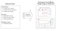
Parameter Estimation
In Transient Stability Analysis, if the influence of induction motors is

perceived to be crucial to the stability of the system or if the motor
acceleration or reacceleration profiles are to be analyzed in detail,
their dynamic model should be specified in the study. The motor
dynamic model is comprised of the following:

a) Motor Equivalent Circuit
b) Motor Load Torque Characteristics
c) Motor, Load, and Coupling Inertias

The above may be available from the motor manufacturer. More
often than not, rather than the motor equivalent circuit, the
manufacturer provides machine performance characteristic data
(i.e. Motor Speed Vs Torque, Current, and Power Factor curves).
However, even with this machine performance characteristic
data only, ETAP can be able to estimate a corresponding
equivalent circuit model of the motor using the PARAMETER
ESTIMATION program.


Sample of determining the above data from the Motor
Characteristic Curves


Monday, March 30, 2009

Estimation of Induction Motor Parameters

Estimation of Induction Motor Parameters Based on
Field Test Coupled with Genetic Algorithm


Abstract
This paper proposed a technique for estimating the
parameters of three-phase induction motor in order to conduct
on-site energy audits of existing motors, which are then used to
project a cost savings. This proposed technique uses only a few
sets of data (voltage, current, speed, power factor or torque if
possible) from the field test of motor (on-site), instead of the noload
and blocked rotor tests, coupled with the genetic algorithm
for evaluating the equivalent circuit parameters. Once these
parameters are known it is possible to obtain the operating
performances (50-100%) of the motor such as efficiency, current,
torque. This technique could be suitable for the general purpose
drive applications when the motor cannot operate at no-load
since its shaft is permanently connected to its load. To illustrate
how well the performances of the estimated model matches that
of the actual motor obtained from load test, the results of 3 HP
and 5 HP induction motors will be presented and compared.

more pdf


A SIMPLE APPROACH TO INDUCTION MACHINE
PARAMETER ESTIMATION


Abstract
The paper deals with a simple estimation procedure of the
squirrel-cage induction motor parameters, like resistances and
inductances, considering the data from the machine nameplate.
First is presented the analytical calculation according to the
conventional steady-state per-phase equivalent circuit, neglecting
the ironcore losses. The magnitude of stator-, air-gap and rotor
fluxes, required as references by field-controlled scalar and vector
control systems, are also determined. For validation of the identified
parameters there are presented two simulation structures containing
the motor dynamic d-q model, based on the state equations related to
a stator-fixed and to a general oriented reference frame.
The simulation results are analyzed using the space-phasor theory.


Fig. 1. Steady-state electrical
(a) and magnetical
(b) equivalent circuits defined also for zero frequency

more pdf


PARAMETER IDENTIFICATION OF AN INDUCTION MOTOR
USING FUZZY LOGIC CONTROLLER

Abstract.
The paper describes a method of parameter identification
of an equivalent circuit of an induction motor using fuzzy logic
controller. The method is based on the step-by-step approach in
which the parameters are calculated from an equivalent circuit and
real measured speed-torque characteristic. The displacement of
two characteristics as a complex input variable for a fuzzy logic
controller is used. In order to demonstrate the reliability of the
proposed methods, an example of speed-torque characteristic of
induction motors and parameter determination of an equivalent
circuit is discussed.

The algorithm of computer controlled determination of induction
motor characteristics and parameters

Sunday, March 29, 2009

Equivalent circuits of three-phase induction motor

The equivalent circuits as in Fig. 1 can be represented the
steady state behavior of a three-phase induction motor.
Where
R1 : stator resistance
X1 : stator leakage reactance
Rc : core loss resistance,
Xm : magnetizing reactance,
R2 : rotor resistance referred to stator,
X2 : rotor leakage reactance referred to stator,
Xeq : equivalent leakage reactance ( X1 + X2 ),
s : slip


From the six-impedance and approximate equivalent circuits,
the equations of stator current ( I1 ) and power factor ( PF )
can be expressed as in (1) and (2) respectively.


Fig. 1. Equivalent circuits of three-phase induction motor
a) six-impedance b) approximate


Source pdf
http://www.eng.mut.ac.th/upload_file/product/43.pdf

Friday, March 27, 2009

INDUCTION MOTORS ANALYSIS

Induction motor starting can be analyzed using electrical, mechanical,
and thermal models which interact as diagrammed in Figure 1. In the
electrical model, the voltage, V, and the slip, S, determine the rotor
current. The summation of all torques acting on the motor shaft
comprises the mechanical model. Here, the driving torque developed
by the motor is resisted by the load torque and the moment of inertia
of all the rotating elements, all of which are slip dependent. The thermal
model is the equation for heat rise due to current in a conductor
determined by the thermal capacity, the thermal resistance, and the slip
dependent I2R watts. As the ultimate protection criteria, the thermal
model is used to estimate the rotor temperature, U, resulting from the
starting condition with initial temperature U0. A recursive solution using
finite time increments is used because the rotor impedance changes
continuously with slip.


Figure 1: Motor Analysis Block Diagram

Index

1. DEFINING THE ELECTRICAL MODEL


Figure 3: Motor Equivalent Circuit

2. DEFINING THE MECHANICAL MODEL


Figure 5: Contour of Load Torque

3. DEFINING THE THERMAL MODEL


Figure 10: Motor Thermal Model

4. THE MOTOR ANALYSIS

More pdf

Sunday, February 1, 2009

Calculation Equivalent of induction motors program

Calculation the equivalent circuit of AC induction motors program

REMCAD


The program is designed for users and designers of electric-motor
drives with AC induction motors powered by Frequency inverters.

DESCRIPTION OF THE PROGRAMThe RemCad program can be
used for:1.1 the storage of basic machine data1.2 the calculation
and drawing of the characteristics on the basis
of the Equivalent Circuit (Torque, PowerFactor, Efficiency,
InputPower etc.)1.3 The export of the calculated data
The calculation and drawing of the characteristics on the basis of
the equivalent circuitThe following characteristics are drawn and
calculated:- the Moment characteristic dependant on frequency
and current
(current being the parameter)- the PowerFactor characteristic
dependant on frequency and current (current being the parameter)-
the Efficiency characteristic dependant on frequency and current
(current being the parameter)- the InputPower characteristic
dependant on frequency and current (current being the parameter)
The calculation is performed on the basis of the equivalent circuit
of the asynchronous machine.


Fig 1. Equivalent Circuit Diagram of AC induction machine

more

Relate Posts