Saturday, October 2, 2010

Dynamic Model , Proportional Integral and Derivative Control of Brushless DC Motor


Proportional Integral and Derivative Control of Brushless DC Motor

Abstract
Brushless DC (BLDC) motors are one of the electrical drives that are rapidly
gaining popularity, due to their high efficiency, good dynamic response and low
maintenance. In this paper, the modeling and simulation of the BLDC motor was done
using the software package MATLAB/SIMULINK. A speed controller has been designed
successfully for closed loop operation of the BLDC motor so that the motor runs very
closed to the reference speed. The simulated system has a fast response with small
overshoot and zero steady state error.

http://www.eurojournals.com/ejsr_35_2_05.pdf


Dynamic Model of the BLDC Motor

It is assumed that the BLDC motor is connected to the output of the inverter, while the inverter input terminals are connected to a constant supply voltage, as shown in Fig.1. Another assumption is that there are no power losses in the inverter and the 3-phase motor winding is connected in star.


http://www.eurojournals.com/ejsr_35_2_05.pdf

Wednesday, September 15, 2010

Basic brushless motor control


The control consists of logic circuitry and a power stage to drive the motor. The control’s logic circuitry is
designed to switch current at the optimum timing point. It receives information about the shaft/magnet
location (signals from the Hall devices), and outputs a signal, to turn on a specific power device, to apply
power from the power supply (not shown) to specific windings of the brushless motor.

http://www.motioncontrolonline.org/files/public/BrushlessOperation.pdf

Brushless DC Motor Control Made Easy

INTRODUCTION
This application note discusses the steps of developing
several controllers for brushless motors. We cover sensored,
sensorless, open loop, and closed loop design.
There is even a controller with independent voltage and
speed controls so you can discover your motor’s characteristics
empirically.

The code in this application note was developed with
the Microchip PIC16F877 PICmicro® Microcontroller, in
conjuction with the In-Circuit Debugger (ICD). This
combination was chosen because the ICD is inexpensive,
and code can be debugged in the prototype hardware
without need for an extra programmer or
emulator. As the design develops, we program the target


http://www.jimfranklin.info/microchipdatasheets/00857a.pdf

Tuesday, March 16, 2010

Brushless DC Motor modification and winding


Brushless DC Motor modification
My first speed 300 motor died after about half year of flying. In order to have better performances, I decide to change the engine into brushless. There are several choices of brushless motor in the market, such as the Hacker and Astro. By the way, there has been a mania for using modified CD-Rom motor in our RC models. Needless to say, I have joined the groups that are trying to find out the potential of these wildly available and low-price CD-Rom motors. 


Brushless motor winding by Utah Fyers #1 video
Video Radio control electric brushless motor winding tutorial  


Brushless motor winding by Utah Fyers #2 video
Tutorial on brushless motor winding presented by Utah Flyers.


Buy Cheap Brushless DC Motor

Sunday, March 14, 2010

Waveform of a Brushless DC Motor


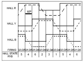
Brushless DC Motor COMMUTATION SEQUENCE


Figure shows an example of Hall sensor signals with
respect to back EMF and the phase current. Figure 8
shows the switching sequence that should be followed
with respect to the Hall sensors. The sequence numbers
on Figure correspond to the numbers given in Figure 8.
Every 60 electrical degrees of rotation, one of the Hall
sensors changes the state. Given this, it takes six steps
to complete an electrical cycle. In synchronous, with
every 60 electrical degrees, the phase current switching
should be updated. However, one electrical cycle
may not correspond to a complete mechanical revolution
of the rotor. The number of electrical cycles to be
repeated to complete a mechanical rotation is determined
by the rotor pole pairs. For each rotor pole pairs,
one electrical cycle is completed. So, the number of
electrical cycles/rotations equals the rotor pole pairs.


BLDC Motor Waveforms
Figure is a graphical representation of the BEMF formulas
computed over one electrical revolution. To
avoid clutter, only the terminal A waveform, as would
be observed on a oscilloscope is displayed and is
denoted as BEMF(drive on). The terminal A waveform
is flattened at the top and bottom because at those
points the terminal is connected to the drive voltage or
ground. The sinusoidal waveforms are the individual
coil BEMFs relative to the coil common connection
point. The 60 degree sinusoidal humps are the BEMFs
of the driven coil pairs relative to ground. The entire
graph has been normalized to the RMS value of the coil
pair BEMFs.


Notice that the BEMF(drive on) waveform is fairly linear
and passes through a voltage that is exactly half of the
applied voltage at precisely 60 degrees which coincides
with the zero crossing of the coil A BEMF waveform.
This implies that we can determine the rotor
electrical position by detecting when the open terminal
voltage equals half the applied voltage.


BEMF waveforms and the zero-crossing points
The fact that one of the windings is not energized during each sector is an important characteristic of six-step control that allows for the use of a sensorless control algorithm. When a BLDC motor rotates, each winding generates BEMF, which opposes the main voltage supplied to the windings according to Lenz’s Law. The polarity of this BEMF is in the opposite direction of the energizing voltage. Figure 2, below, shows ideal BEMF waveforms and the zero-crossing points.


Waveform of a Brushless DC Motor ESC video
E-flite EFLA311, 20 A ESC driving an E-flite 450 motor.


Buy Cheap Brushless DC Motor

Friday, March 12, 2010

Brushless DC Motor Maintain Video


Brushless dcmotor maintain Part 1
Video how to take off brushless dc motor


Brushless dc motor maintain Part 2
Video how to clean brushless dc motor


Brushless dc motor maintain Part 3
Video how to assemble brushless dc motor


Buy Cheap Brushless DC Motor


Tuesday, March 9, 2010

Brushless Motor Construction


Brushless DC (BLDC) Motor Fundamentals


CONSTRUCTION AND OPERATING PRINCIPLE
BLDC motors are a type of synchronous motor. This
means the magnetic field generated by the stator and
the magnetic field generated by the rotor rotate at the
same frequency. BLDC motors do not experience the
“slip” that is normally seen in induction motors.
BLDC motors come in single-phase, 2-phase and
3-phase configurations. Corresponding to its type, the
stator has the same number of windings. Out of these,
3-phase motors are the most popular and widely used.
This application note focuses on 3-phase motors.


Brushless DC Motor - Basic structures


The construction of modern brushless motors is very similar to the ac motor, known as the permanent magnet synchronous motor. Fig.1 illustrates the structure of a typical three-phase brushless dc motor. The stator windings are similar to those in a polyphase ac motor, and the rotor is composed of one or more permanent magnets. Brushless dc motors are different from ac synchronous motors in that the former incorporates some means to detect the rotor position (or magnetic poles) to produce signals to control the electronic switches as shown in Fig.2. The most common position/pole sensor is the Hall element, but some motors use optical sensors.


Brushless Motor Construction Video
Machining A Brushless Motor with a lathe and drill press. Just a quick slide show of some motor contsruction tips before I added a small milling machine to my hobby shop. John  


Buy Cheap Brushless Motor


Friday, March 5, 2010

Brushless motor winding

Brushless DC Motor modification

A picture is worth hundreds of words. Here is a wiring diagram for the star configuration that I have found from the net. you are better to do this with great circumspection or it would be easily end up with a burned ESC. The first photo shown above is one group of the windings on the stator. Two groups are wound in the second photo while all three groups are wound in the last photo. The starts of each three groups are soldered together and the three ends are the phase wires that connect to the brushless controller.


Brushless Motor Winding Diagrams


The 'standard' Star diagram for
9-tooth stators & 12 magnets


Brushless motor winding by Utah Fyers #1
Radio control electric brushless motor winding tutorial video

Brushless motor winding by Utah Fyers #2
Tutorial on brushless motor winding video presented by Utah Flyers. 


Buy Cheap Brushless Motor

Monday, March 1, 2010

Home Built Brushless DC Motor Video


Brushless DC Motor
Video of a Home Built Brushless DC Motor


Brushless DC motor
Three students (16-17 years old) from the "Stedelijk College" in Eindhoven, the Netherlands designed and made this motor in one day! The motor turns with approximately 2000 rpm!


Homemade brushless motor
This is my homemade brushless motor. Or you could call it a fan! It's made from old junk and surplus components mostly. Better description is in the video!


home made brushless dc motor
Video home made brushless dc motor battery: Align 3 cell li-po 11.1v Reed switch 8 neodymium magnets no bearings were used (performance would have improved greatly if bearings were used on the spindle)


Buy Cheap Brushless DC Motor 

Thursday, February 25, 2010

Basic Brushless DC Motor


Basic brushless DC Motor


However, if, at the appropriate time, current is shut off in winding “R”, and turned on in winding “S”, then the rotor continues to move. Again at the appropriate time, shut off “S” and turned on “T”. By continuation of this timing sequence, complete rotation occurs. What is occurring, is that the field set up by the stator is being switched, and the rotor tries to catch up to it.

In this example, the explanation was simplified by exciting only one winding at a time. In reality, the stator consists of a three phase Y–connected winding, and two or three windings are actually energized.. This makes efficient use of windings and development of higher motor torques.

Basic Brushless Motor Basics


In its simplest form, a brushless dc motor consists of a permanent magnet, which rotates (the rotor), surrounded by three equally spaced windings, which are fixed (the stator). Current flow in each winding produces a magnetic field vector, which sums with the fields from the other windings. By controlling currents in the three windings, a magnetic field of arbitrary direction and magnitude can be produced by the stator. Torque is then produced by the attraction or repulsion between this net stator field and the magnetic field of the rotor.


Basic Brushless DC Motors
Conventional dc motors are highly efficient and their characteristics make them suitable for use as servomotors. However, their only drawback is that they need a commutator and brushes which are subject to wear and require maintenance. When the functions of commutator and brushes were implemented by solid-state switches, maintenance-free motors were realised. These motors are now known as brushless dc motors. In this chapter, the basic structures, drive circuits, fundamental principles, steady state characteristics, and applications of brushless dc motors will be discussed.
more


Buy Cheap Brushless DC Motor

Wednesday, February 17, 2010

Brushed DC Motor control by using PIC Microcontroller


Low-Cost Bidirectional Brushed DC Motor Control
Using the PIC16F684
INTRODUCTION
This application note discusses how to use the
Enhanced, Capture, Compare, PWM (ECCP) on the
PIC16F684 Microcontroller for bidirectional, brushed DC (BDC) motor
control. Low-cost brushed DC motor control can be
used in applications such as intelligent toys, small
appliances and power tools. The PIC16F684 takes
Microchip's Mid-Range Family of products to the next
level with its new ECCP peripheral. The ECCP
peripheral builds on the technology of the CCP module
with added features such as four PWM channels for
easy bidirectional motor control through the hardware.
This application note focuses on using the ECCP in
PWM mode using the full-bridge configuration. Using
the ECCP allows easy interfacing to a full-bridge
configuration for bidirectional BDC motor control.


Brushed DC Motor control by using PIC microcontroller
I used PIC microcontroller to realize the control of BLDC motor. In the video, you can observe how the PID parameter affect the performance of motor. The different magnitudes (due to different PID parameters)


Efficient Brushless DC motor and Permanent Magnet Synchronous Motor Control
Demonstration of advanced sensorless algorithms such as field oriented control and trapezoidal control using sinusoidal drive for Brushless DC (BLDC) and Permanent Magnet (PM) Synchronous Motors


Buy PIC Microcontroller Project Book

Sunday, February 14, 2010

Brushless DC Motor Control using PIC18 Microcontroller Video

Video Developing Brushless DC (BLDC) motor control using PIC18Fxx31 Microcontroller - Part 1
BLDC motors can be designed to operate from a high voltage or low voltage source. The following seminar explores BLDC control using PIC18F Microcontroller devices.


Video Developing Brushless DC (BLDC) motor control using PIC18Fxx31 Microcontroller - Part 2


Video Developing Brushless DC (BLDC) motor control using PIC18Fxx31 Microcontroller - Part 3


Video Developing Brushless DC (BLDC) motor control using PIC18Fxx31 Microcontroller - Part 4


Buy PIC18 Microcontroller Book

Monday, February 8, 2010

Sensorless Brushless DC Motor control using a Microcontroller Data and algorithm

Sensorless Brushless DC Motor Control with Z8 Encore! MC™ Microcontrollers
Abstract
This application note discusses the closed loop control of a 3-Phase Brushless
Direct Current (BLDC) motor using the Z8 Encore! MC™ Family of
Microcontrollers series microcontrollers (MCUs). The Z8 Encore! MC™ product
family is designed specifically for motor control applications, featuring an on-chip
integrated array of application-specific analog and digital modules. This in turn
results in fast and precise fault control, high system efficiency, and “on-the-fly”
speed / torque and direction control, as well as ease of firmware development for
customized applications.

This article further discusses ways on how to implement a sensorless feedback
control system using a “Phase Locked Loop” along with Back EMF sensing.


Sensorless control of 3-phase brushless DC motors
Introduction
This application note describes how to implement sensorless commutation control
of a 3-phase brushless DC  motor (BLDC) with the low cost ATmega48
microcontroller. A general solution, suitable for most 3-phase BLDC motors on the
market is presented. The full source code is written in the C language, no assembly
is required. Adaptation to different motors is done through the setting of parameters
in the source code.

The ATmega48/88/168 devices are all pin and source code compatible. The only
difference is memory sizes. This application note is written with ATmega48 in mind,
but any reference to ATmega48 in this document also applies to ATmega88/168.


Brushed DC motor control using the LPC2101 microcontroller
Introduction
This application note demonstrates the use of a low cost NXP Semiconductors LPC2101 microcontroller for bidirectional brushed DC motor control.
The LPC2101 is based on a 16/32-bit ARM7 CPU combined with embedded high-speed flash memory. A superior performance as well as their tiny size, low power consumption and a blend of on-chip peripherals make these devices ideal for a wide range of applications. Various 32-bit and 16-bit timers, 10-bit ADC and PWM features through output match on all timers, make them particularly suitable for industrial control. 

Brushed DC (Direct Current) motors are most commonly used in easy to drive, variable speed and high start-up torque applications. They have become widespread and are available in all shapes and sizes from large-scale industrial models to small motors for light applications (such as 12 V DC motors).


Sensorless BLDC Motor Control Using MC9S08AC16
Introduction
This application note describes the design of a 3-phase
sensorless BLDC motor drive with Back-EMF
zero crossing. It is based on Freescale’s MC9S08AC16
that can be effectively used for motor-control
applications.

The concept of the application is that of a speed-closed
loop drive using Back-EMF zero crossing technique for
positional detection. It serves as an example of a
sensorless BLDC motor control system using
Freescale’s MCU and 3-Phase BLDC/PMSM
Low-Voltage Motor Control Drive. It also illustrates
the usage of general on-chip peripherals for
motor-control applications.
This application note includes a description of the
controller features, basic BLDC motor theory, system
design concept, hardware implementation, software
design including the FreeMaster software visualization
tool, application setup, and demo operation.


Sensorless Brushless DC Motor Control with PIC16 Microcontroller
INTRODUCTION
There is a lot of interest in using Brushless DC (BLDC)
motors. Among the many advantages to a BLDC motor
over a brushed DC motor, we can enumerate the
following:
• The absence of the mechanical commutator
allows higher speeds
• Brush performance limits the transient response
in the DC motor
• With the DC motor you have to add the voltage
drop in the brushes among motor losses
• Brush restrictions on reactance voltage of the
armature constrains the length of core reducing
the speed response and increasing the inertia for
a specific torque
• The source of heating in the BLDC motor is in the
stator, while in the DC motor it is in the rotor,
therefore it is easier to dissipate heat in the BLDC
• Reduced audible and electromagnetic noise


Brushless DC Motors Theory and Driver Circuit

Buy Brushless  Motor  Speed Controller

Friday, January 8, 2010

Sensorless Brushed DC Motor control using a dsPIC Data and algorithm

This web seminar explains a sensorless Brushless Direct Current (BLDC) motor control algorithm, implemented using the dsPIC® digital signal controller (DSC).

Sensorless Brushed DC Motor control using a Majority Function Part 1 of 2


Sensorless Brushed DC Motor control using a Majority Function Part 2 pf 2


How a BLDC controller work - Giovanni Garraffa


Using the dsPIC30F for Sensorless BLDC Control
INTRODUCTION
This application note describes a fully working and
highly flexible software application for using the
dsPIC30F to control brushless DC (BLDC) motors
without position sensors. The software makes
extensive use of dsPIC30F peripherals for motor
control. The algorithm implemented for sensorless
control is particularly suitable for use on fans and
pumps. The program is written in C and has been
specifically optimized and well annotated for ease of
understanding and program modification.


more


Sensorless BLDC Motor Control Using dsPIC30F2010
INTRODUCTION
This application note describes how to provide sensorless
BLDC motor control with the dsPIC30F2010
Digital Signal Controller. The technique used is based
on another Microchip application note: Using the
dsPIC30F for Sensorless BLDC Control (AN901).
This application note explains how to apply the
dsPIC30F2010 device to the hardware and software
described in AN901, which uses the dsPIC30F6010
device and dsPICDEM™ MC1 Motor Control Development
Board. The 80-pin dsPIC30F6010 has 144
Kbytes of Flash Program Memory, 8 Kbytes of RAM
available and abundant I/O. The 28-pin
dsPIC30F2010, on the other hand, has limited I/O, only
12 Kbytes of Flash program memory and 512 bytes of
RAM. As you can see, the resources are finite.
This application note prescribes changes to the hardware,
software and user interface described in AN901
to facilitate the easy transfer of the code to the
dsPIC30F2010 device.


more

Buy  Brushless DC Motor control